|
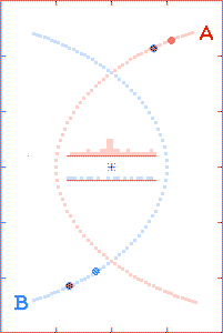
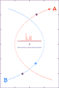
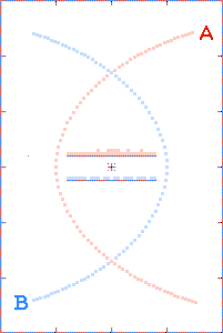
The animations are run as though there is a
radio beacon associated with each component of the binary. Every
tenth of a second the beacons transmit their x and y
coordinates (with respect to the system's center of gravity) and the
time t of the transmissions.
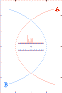
The grey dots show what observers, located as described above, could
tell about each component's path history based on received x,
y, and t information. The red and blue dots show what the
observer could tell, based on the transmitted x and y
positions, but with the time coordinate τ derived from the
arrival times of the radio signals.
The histograms in the center of the animations show the filling of
transmission-arrival-time bins. At the completion of each
run, the bin totals form crude light curves (at the specified
observer distances) for the encounter events.
Highly-elliptical orbits are used to approximate near-perihelion
parabolic (or hyperbolic) paths for stars involved in chance
encounters.
In the third animation, the binary-to-observer distance is such that
briefly the c+v time-advanced later emitted light arrives
at the distant observer's location prior to the c-v time-retarded
earlier emitted light. (In Einstein's words, the light seems to
get "all mixed up.") Note the double-spiked light curve. (In the
time-interval between the spikes, the starlight arriving at the observer's
location even behaves as though time's arrow was reversed.)
There are a lot of (yet-to-be
explained) double-peaked Gamma-Ray Bursts.
How it's done.
Code was written in Microsoft QuickBASIC to roughly model
gravitational interactions between two objects. Both objects were given
the same arbitrary mass, and at t=0, object(A) was placed at
x=0, y=0 and object(B) was placed at x = -1,
y = 0. The program's gravitational constant, and the initial object
velocities (again, with arbitrary values) were assigned and adjusted so
that gravity driven parabola-like paths resulted.
The incremented times, and associated x and y positions for objects(A)
and (B), were transferred to columns in a Microsoft Excel
spreadsheet. Position coordinates for times prior to t=0 are time-wise
mirror-images of those already entered.
Computational columns were then added to the spread sheet to calculate
everything needed to determine the c+v arrival times at a remote
location. The arrival times were assigned to discrete time bins. The
number of "hits" that accumulates in each time bin serve to produce
a rough light curve for the object.
By using Paint Shop Pro, the real object(A) and (B) postions and their
c+v apparent positions-versus-times were incorporated into graphics
images (one image per time bin) and the sequence was combined to make
the animation.
The QuickBASIC program used to generate the binary x and y positions is:
par65100.bas.
The Excel files used in creating the animations (so far) are:
ep65100a.xls, and
ep65100q.xls.
Computational Notes
The the equation used in the spreadsheets to calculate light speed for
binary components (A) and (B), with respect to the specially
located observer, uses the vector relation C + V dot r,
which is equivalent to C + V cos(θ).
Here, C is the speed of light, V is the instantaneous
orbital velocity for the binary component, r is the unit vector
along the source-to-observer line-of-sight, and
θ is the angle between the two. A more correct procedure,
but harder computationally, would be to determine the required
offset direction for C, compared to the
line-of-sight.
The offset C would then be vectorially added to
V, to get the real C+V along the line-of-sight.
The following graphs show the difference between the two ways of doing
business. (Distances shown are multiples of 1 million km and
speeds are multiples of 1 million km/sec.)
In A, a stationary star is shown as being located 300 million km
from an observer. Light, traveling at 300 million km/sec, takes one
second to reach the observer.
B shows the C + V cos(θ) scheme used to calculate
light speeds, and hence travel times, in the spreadsheets. (This
method is not vectorially correct.)
In C, correct vectors for C and V are used. It
can be seen that the improved C', is only slightly
better (0.27 percent for this example) than the value of
C' shown in B.
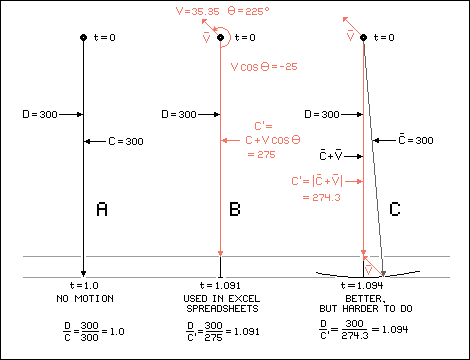
Enroute Light Speed and Travel Time Computation Schemes
Related Webpages
Orbiting Binary Stars (My use of the phrase "priviledged views" above was stolen from this page.)
Thanks to the visitor from (128.123.5.66) for finding a broken link to this source [09 Sep 2010].
|